Innovation and development of SO3 multitube film sulphonation reactor of Weixian
Apr 21, 2023
Innovation and development of SO3 multitube film sulphonation reactor of Weixian
Shumin Li, Chen Li, Gongjian Cai
(WEIXIAN NANJING SCIENCE TECHNOLOGY CORP. LTD. Jiangsu Nanjing 201142)
Abstract: this article introduces the innovation and experiences of a type of SO3 multitube film sulphonation reactor in its design and manufacturing. Mainly explains the relations among design and manufacturing of reactor’s main parts, sulphonation/sulphoacid reaction, and quality control, production stability and equipment reliability. Concludes that WEIXIAN’s SO3 multitube film sulphonation reactor is superior to similar Italian equipment, in term of key performance and reliability.
Key words: SO3 film sulphonation, multitube film sulphonation reactor, innovation, development
Preface:
In March 1995, WEIXIAN independently designed and manufactured domestically a 6-tube multitube film sulphonation pilot plant. Its capacity was 250kg/h, and tested LAB, BAB, HAB, FA, AEO and α-olephin as raw material for batch OEM produce.
Next, we will introduce WEIXIAN’s innovation and development in regards of SO3 multitube film sulphonation reactor.
1. The reaction tubes of SO3 multitube film sulphonation reactor
Since 1995, the first 6-tube film reactor, WEIXIAN always keep improving and perfecting the design and manufacturing process of sulphonation reactor. Basically, the length, internal diameter and thickness influence the heat transfer, material transfer and reaction speed. By countless times experiments, optimal data have been obtained.
The internal tolerance and surface finish difference of reactor tube not only influence heat transfer and material transfer, but also influence differential SO3 and organic material mole ratio, which is crucial for dioxane control when producing SLES. So, while we manufacturing one batch of reaction tubes (normally 1000 tube/batch), we make sure using one mold for the cold working, which ensure each tube’s internal and external diameter tolerance is consistent.
Then the reaction tubes will be putt into a 1040℃ furnace, for removing the stress between molecules due to the cold working. In order to keep the surface finish degree (like mirror) benefit from cold working, there should be no oxygen under this 1040 ℃ condition, which is the most advanced oxygen isolating stress relieving technology. We abandoned the artificial sanding method which can’t make the surface as smooth as mirror. With perfect surface finish degree, side reaction can be reduced effectively, it is crucial in regards of decreasing dioxane content in SLES.
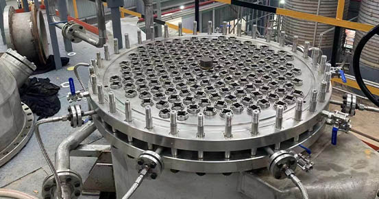
2. Distribution head and SO3 nozzle
Please see Drawing 1 for distribution head and SO3 nozzle.
There are special designs for distribution head. The sealing between distribution head and shell side cooling water is able to accept enough pressing force, so that reactor shell can bare pressure up to 0.6 mpa, while the pressure of returning water which enters reactor is normally ≤0.05 mpa. That is why the recycle cooling water is able to carry with higher pressure.
In terms of distribution head and SO3 nozzle processing, we also ensure the consistency, and simplify the first start-up commissioning (see diagram 1 and 2) and extend the interval of reactor cleanings. Especially while producing AOS, the optimizations decrease the lower operation limit of reactor. Because of little feeding volume of α-olephin, the distributing and balancing ability of reactor’s liquid film have to be increased while operating under lower operation limit.
Diagram 1 Zhitong system 37-tube reactor first calibration flow rate deviation distribution
No.
Flow rate deviation
Tube quantity
Gasket thickness
1
Less than ±1.5%
19 tubes
2.00mm
2
±1.5%~±2.5%
13 tubes
2.00mm
3
+3.7%
1 tubes
2.00mm
4
-3.6%
1 tubes
2.00mm
5
-5.2%
1 tubes
2.00mm
6
+8.8%
1 tubes
2.00mm
7
-6.5%
1 tubes
2.00mm
Diagram 2 Zhitong system 90-tube reactor first calibration flow rate deviation distribution
No.
Flow rate deviation
Tube quantity
Gasket thickness
1
Less than ±1.5%
33 tubes
2.00mm
2
±1.5%~±2.5%
31 tubes
2.00mm
3
±2.5%~±3.0%
13 tubes
2.00mm
4
±3.0%~±3.5%
8 tubes
2.00mm
5
-4.7%
1 tubes
2.00mm
6
+5.6%
1 tubes
2.00mm
7
-8.4%
1 tubes
2.00mm
8
+7.3%
1 tubes
2.00mm
9
+8.9%
1 tubes
2.00mm
As you can see from the diagrams above, the consistent processing of distribution heads and nozzles minimize each reaction tube’s original flow distributing tolerance, and make adjustment easier.
3. Tube sheet and organic material distribution chamber
Regarding the tube sheets of 120/144/180 tube reactor, 25% thickness is increased. So that rigidity is increased, tube sheet would not be transformed much and the tightness of SO3 sealing would be improved.
Also, The height of organic distribution chamber is increased by 8-12 mm (see Drawing 1). It is beneficial for large capacity reactor’s organic material distributing.
Drawing 1 Drawing 2
4. The sealing format between SO3 and organic material
The increase of organic material distribution chamber height and improvement of shell pressure bearing ability are benefited from the special design of sealing format between SO3 compression nut, tube sheet 1 and tube sheet 2. As Drawing 1, at the top is the first seal of tube sheet 1, that consists of a V-shape gasket (Creep-resistant special teflon) and a O-shape gasket (Anti-oleum fluororubber). That means double safety, each of them ensure 100% isolate SO3 from tube sheet 1’ screw thread and organic material distribution chamber. Therefore, the sealing is very reliable and solved the headache problem that the compression nuts sealing of Italian’s reactor is unreliable, sometimes get rusted and can’t open.
As shown in Drawing 1, the second seal is Z-shape creep-resistant Polytetrafluoroethylene plano-concave gasket, which isolates organic material from SO3 in the nozzle inner wall. This special design is efficient and the locking torque for compression screw heads is only the half of two-direction sealing (which is Ballestra’s, Drawing 2 shows the structure of Ballestra’s distribution head). With only half locking torque, the Tubesheet 1 will has less deformation, especially for big capacity reactors. It solves the problem that after tightening all compression screw heads, you may find the first screw head get loosen again. That consolidates the foundation of design and manufacturing of 180, 192 or even more tube reactors.