Improvements of Tube Plate Sealing for Ultra-Large Sulfonator
Jul 17, 2026
Weixian Technology has improved ultra-large sulphonators (178-240 tubes) and achieved successful operation and wide deployment:
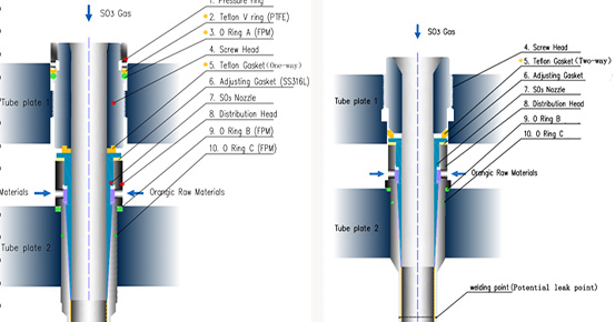
1.Screw Head: As shown in Fig.1, gaskets (Items 1–3) block SO₃, preventing rust or seizure between Tube plate 1 and the screw. Item 5 is a one-way gasket, needing under half the torque of imported equipment, significantly reducing tube plate 1 deformation.
(Fig 1:WEIXIAN Sulphonator head diagram)
(Fig 2: Imported / Copy Sulphonator Head Diagram)
2. Increased Distribution Chamber Height: With the improved screw head sealing, the organic chamber height can be increased by 25% or more, minimizing the flow pressure difference between center and edge for uniform distribution, especially in ultra-large sulphonators with 178/192 tubes or more. Imported sulphonators, limited by the dual-direction gasket (Item 5, Fig.2), are fixed at 32 mm, causing higher pressure differences as size increases.
3. Pressurized Water Return: Improved screw head sealing increases clamping force on sealing ring (Item 9, Fig.1), allowing shell-side cooling water above 0.5 MPa and enabling pressurized water return, eliminating a high-power circulation pump. Imported design (Fig.2, Item 9) has a limiting block, restricting shell-side pressure to ≤0.15 MPa and preventing pressurized return.
Weixian Sulphonator Assembly and Disassembly Guidelines
(A) tube plate Removal Precautions
1. Loosen screw heads (Item 4, Fig.1) after slightly loosening the pressure ring (Item 1), then remove all screw heads.
2. Once screw heads are removed, tube plate 1’s reaction force is gone; central locating rods (1–3) can be lightly unscrewed and removed.
3. Normally, tube plate 1 is removed every 1–2 years. To clean the feed chamber or nozzles, remove only the screws; debris can be vacuumed out.
4. Screw head seals (Items 1–3) can be reused; no replacement needed every time.
(B) tube plate 1 and screw head Installation
1. Position the tube plates 1 and 2 using the three locating tie rods per tube layout; tighten nuts.
2. Install central rods (1–3) with a 400 mm (16”) torque wrench, max 80 kN, tightening evenly; do not use extra leverage.
3. Tighten other tie rod bolts sequentially, finishing diagonally to avoid uneven stress and edge leaks. Check central rods lightly.
4. Install screw heads: loosen pressure ring slightly, tighten screws with torque wrench (35–45 kN, click indicates correct), ensure even load, then tighten compression ring.
(C) Leak and Pressure Test
1. Do not test shell-side leaks with screw heads loose; fully tighten tie rods and screw heads first.
2. During LAB circulation, vent tube plate 1 chamber, check each screw’s PTFE gasket (Item 5) and ring with flashlight or dry paper; ensure no leaks.